
Blog 3 of 4: Hardware, Electronics and Making It Real
The Development Droid
While the final droid was printing, a process that took several weeks, I wasn't waiting around. I had a previously built animatronic Pit Droid that uses the same head servo configuration, so I clipped a camera to its eye socket, ran wires out to the Orin Nano sitting on a desk, and used that as my development platform. It wasn't pretty, but it worked. The head pan and tilt behavior is identical between the two builds, so everything I was developing, the detection pipeline, the tracking logic, the servo control, transferred directly.
That animatronic droid carried the project through the bulk of development. The age classification work, all of it, happened on it. By the time the final droid was painted, assembled, and ready for its arm and torso servos, we had already been through months of iteration and one major pivot. The finished droid didn't get to be the development droid; it inherited a system that had already been through the hard part. Gesture recognition was added once the final droid was nearly complete, which meant the first time I ran it on the finished build was close to the real thing.
The Print and the Paint
The Pit Droid body comes from files by Droid Division, a designer whose work has become the community standard for this character. The animatronic modifications, the parts that allow for head movement and make room for servos, were created by another member of the Droid Division build group and shared with those of us who had already purchased the original files. It's a good example of how these builder communities actually work: the base files give you a starting point, and the community extends them.
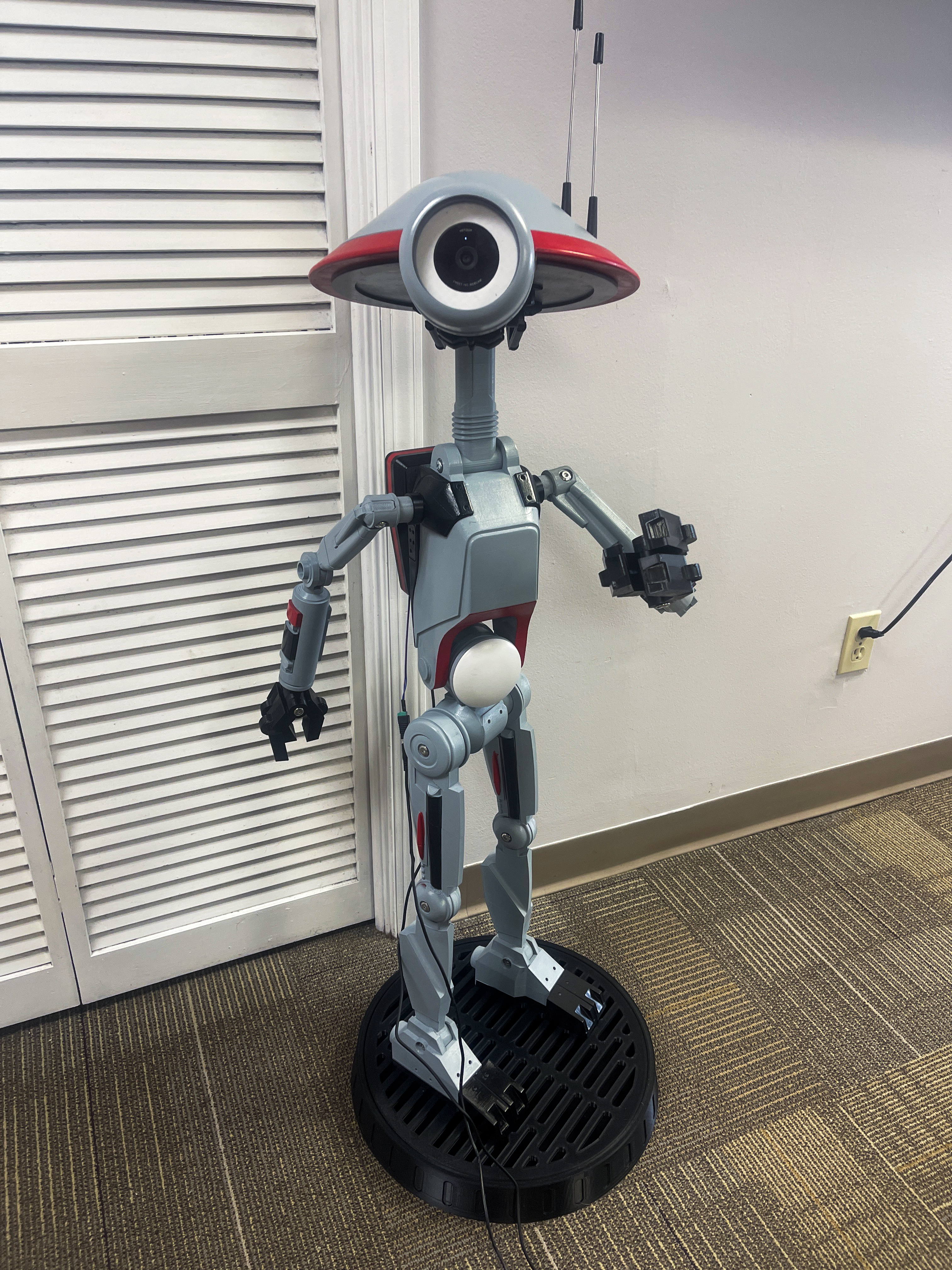
Printing the droid took several weeks spread across many sessions, and the parts came off the printer in grey filament, which turned out to be a happy accident. Before I'd settled on a final paint scheme I was already applying grey filler primer, not knowing I'd eventually be painting it gloss grey anyway. The surface preparation process was multiple rounds of print, sand, prime, sand again, prime again, working to fill the layer lines that FDM printing leaves behind and get a surface smooth enough to hold a clean paint coat. It's the part of a build like this that doesn't photograph well and doesn't get talked about much, but it's where a lot of hours go.
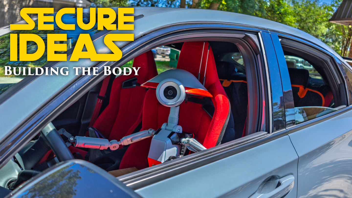
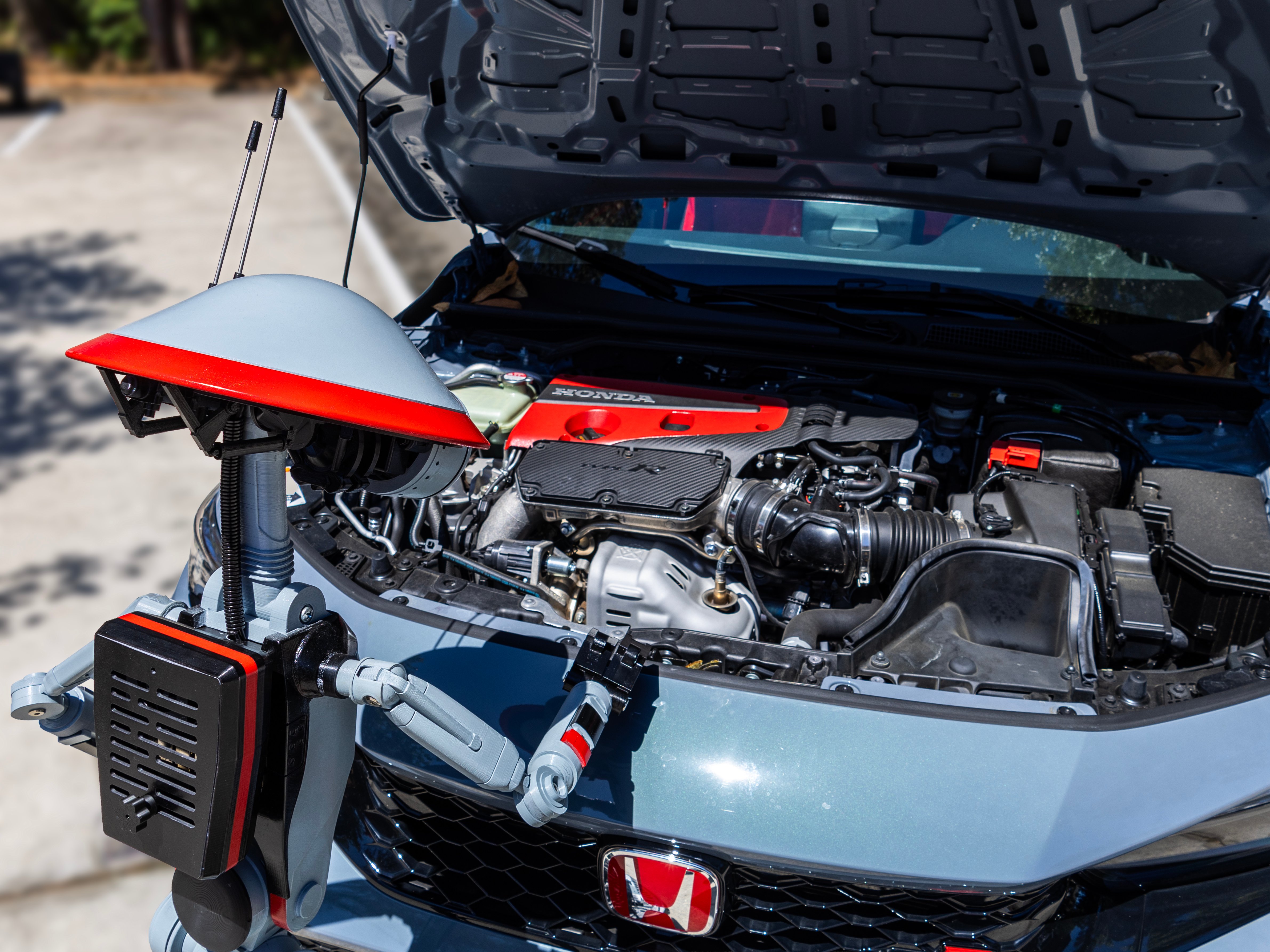
The paint scheme came from a conversation with my coworker Jennifer, who drives a Honda Civic Type-R, primer grey with black and red accents. When I was stuck on what colors to use she suggested it, and it immediately felt right.

Star Wars droids exist in what George Lucas called the "used universe," everything looks weathered, worn, lived-in. My previous Pit Droids are faithful to that aesthetic. This one was different. I wanted something that read as recognizably Star Wars but stood apart from the used look, something that felt clean and modern. A droid built to represent AI rather than a galaxy far, far away's maintenance culture. The Type-R color scheme delivered exactly that.

Fitting the Electronics
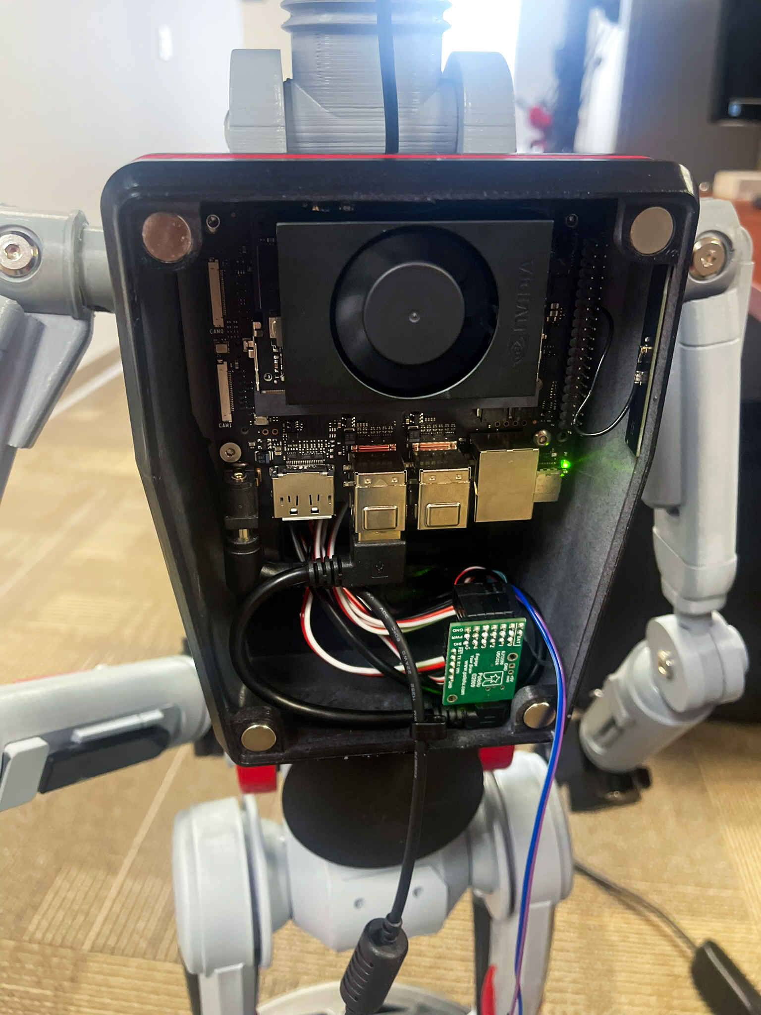
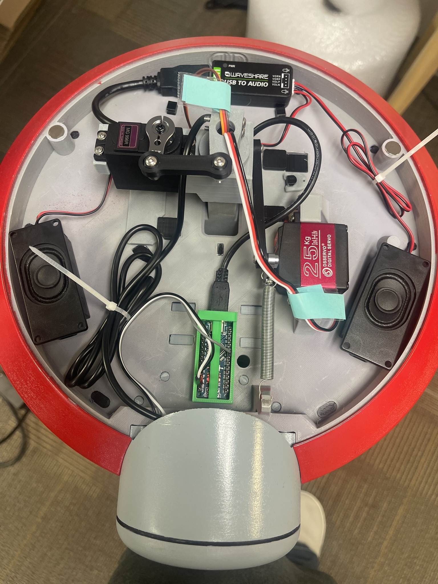
One of the decisions I made early that paid off throughout the build was choosing peripherals that all communicate over USB. The Pololu Maestro servo controller, the Waveshare audio adapter, the camera, and the Arduino Nano driving the LED ring are all USB. That kept the wiring clean and meant the development never depended on the GPIO pins on the Orin Nano, which had given me trouble early on. When everything talks over USB, you spend your time on the actual problem rather than debugging hardware interfaces.
The head unit houses the camera, the LED ring, and the pan and tilt servos, the same configuration as the animatronic droid. The torso and arm servos were new additions that went in during final assembly. The Orin Nano and the rest of the electronics live in the backpack section of the droid, keeping the weight low and the head mechanically simple. Power runs separately for the Orin Nano and the servos, both from wall power, a practical choice for convention use where I know I'll have an outlet nearby and battery life isn't worth the tradeoff in complexity.
The Arm Servo Catch
Installing the arm servos during final assembly was straightforward except for one thing: the right arm moved backward. When the code told it to raise, it lowered. This is a common enough issue with servo installations where the physical orientation of the motor means the direction is inverted relative to what you expect. The fix was simple: invert the channel in code so the right arm's direction is mirrored around center, and it took only a few minutes to catch and correct. It's the kind of thing that only shows up when you actually have the hardware in front of you, which is another reason the animatronic development droid was useful: the arm servos weren't part of that build, so this was a first-assembly discovery on the finished droid.
The Camera Mount Problem
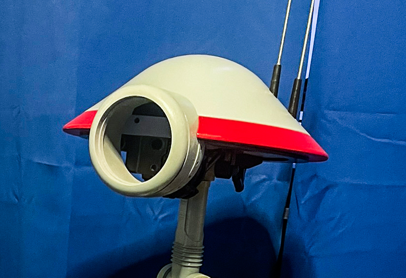
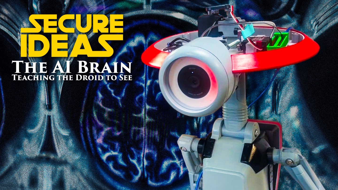
The one moment during the hardware build that required real improvisation was the camera mount. The Pit Droid's eye opening is circular and relatively large, and the camera I chose didn't fit it naturally; it would just rattle around without a proper mount. I jumped into Tinkercad and designed a ring: the camera sits in the center of it, and the ring sits inside the eye socket, holding everything centered and stable. I printed it in white filament.
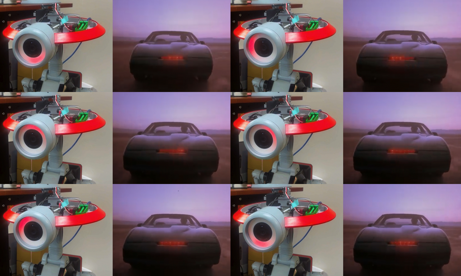
What I didn't plan but appreciated immediately: the white ring acts as a diffuser for the WS2812B LED ring sitting behind it. The LEDs shine through it rather than directly out of the eye, which softens the light and makes the color effects look intentional rather than like exposed electronics. The KITT scanner effect in particular looks much better for it.
For anyone who didn't grow up in the 1980s, KITT was the AI-powered car from the TV show Knight Rider, and its signature visual was a red light that swept back and forth across the front of the car. It was the era's idealization of what AI and autonomy might look like: a single animated light suggesting something was alive and aware inside the machine. Using that same sweeping red pattern as the droid's idle behavior, what it does while scanning for someone to interact with, felt like the right nod to that history. The diffuser ring made it look far better than I expected. We're actually starting to live that reality now, which makes the 40 year old reference feel less like nostalgia and more like acknowledgment.
Putting It All Together
Final assembly, installing the arm and torso servos, routing all the cables, closing up the body, was the point where everything that had been developed on the animatronic stand-in had to actually work inside a finished droid. For the most part it did. The servo channels mapped correctly, the USB connections all came up cleanly, and the tracking behavior that had been tuned for months transferred without needing significant adjustment. The arm servo direction fix was the only real surprise.
Getting the droid running is straightforward once it's set up: it creates its own WiFi network on boot, and starting the detection system is a single command. From there the web interface is accessible from any device on that network, which is how I monitor it and handle any admin controls during a demonstration without touching the droid itself.
Next post: Maker Faire, what the interactions actually looked like, and where the project goes from here.