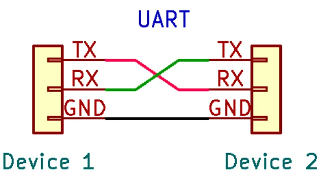

In my previous article, we started to explore the Universal Asynchronous Receiver/Transmitter (UART) interface in general. In that article, we covered the following:
- What the UART interface is
- How it works
- How it's typically used
Today, we will focus less on theory and more on the real world. The goal of this article is to help you:
- Identify possible UART interfaces on PCBs
- Use a multimeter to map out the pins
Finding These on a PCB
When it comes to finding these on a circuit board, visual inspection is usually the simplest way to find UART interfaces. Since I've already explained these are most commonly found in a 4 pin configuration, you'll generally be looking for either a 4 pin header, populated or unpopulated, or perhaps just 4 test points (just exposed dots that are without solder). The photograph below shows a possible UART interface on a PCB, which would be a 4 pin unpopulated header layout.
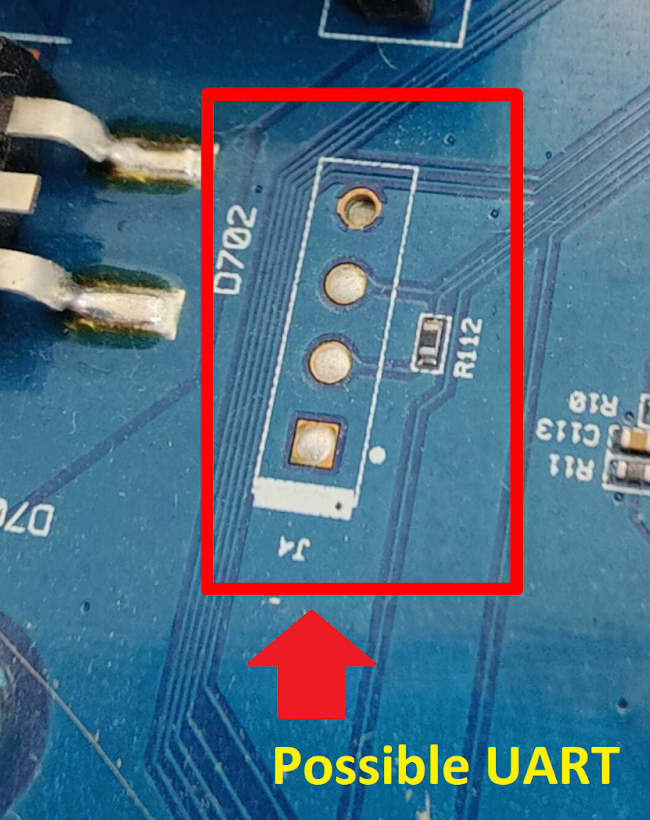
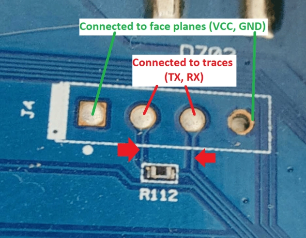
While I haven't confirmed if this is a UART, the possibility looks really good that it might be just that. The two pins on the outside connect to the ground and VCC face planes, while the two pins on the inside have traces running away from them to the nearby MCU (might be a TX and RX pin).
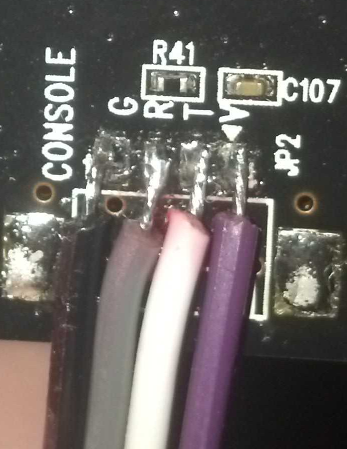
In some cases, you get even luckier and the PCB designer will just straight up label the pins for you with silk screening on the board as shown in the photograph below.
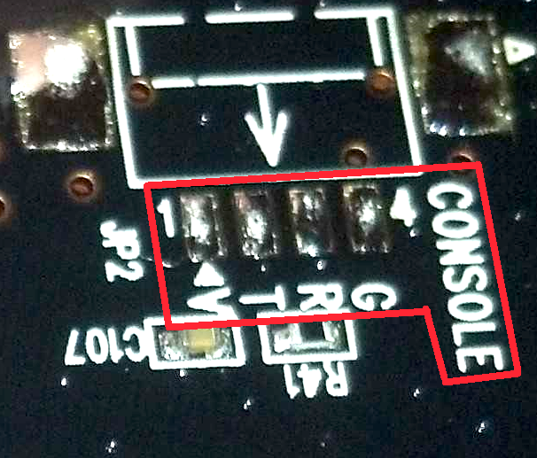
While the pins are labeled V, T, R, and G, it's not hard to infer which are the VCC, TX, RX, and GND pins. So if you see that, it might be worth measuring them out with the multimeter and soldering some jumper wires to them for ease of access later.
Using a Multimeter to Determine the Pinout
Before hooking up to a possible UART port, it might be worth using a multimeter to determine the pinout beforehand, or if this is even a UART pinout to begin with. Just because you found 4 pins doesn't mean it's a UART. It might be for sending power to a daughter board or something else. Either way, here are some tips for trying to learn the pinout via a multimeter.
The GND Pin
The first pin you will want to determine is the GND pin. Using a multimeter, the easiest way to determine that is to use the multimeter's continuity feature. Basically look for the ground at the power connection (barrel plug, USB, battery, etc.), Put one test lead of the multimeter there. Then poke the 4 pins. One of these pins should register continuity. That pin is the GND pin.
The VCC Pin
Now that you know the GND pin, you should determine which one is the VCC pin. For this one you will need to power up the device. Put the multimeter in voltage mode and place the negative test lead on the GND pin. Then using the positive test lead, poke at the others. Two of them might have voltage readings, but you are looking for the one that is providing a steady and constant voltage of either 5 volts or 3.3 volts.
The TX Pin
While testing for the VCC pin, one of the pins might have shown a fluctuating voltage reading. This is because it is transmitting data sporadically. If it's not showing that, power cycle the device. Usually the TX will start sending some sort of data on boot. The pin that you see some fluctuations on is usually the TX pin.
You now know the GND, VCC, and TX Pin, and by process of elimination this means the last pin should be your RX pin.
Conclusion
I hope you enjoyed today's article on finding and mapping UART interfaces on PCBs. In the next blog, we will talk about the hardware and software to allow you to directly interface with UART and the easiest way to discover the correct baud rate for a UART interface.
Ready to connect to the interface?
Now that you can find and map UART pins, the next step is hooking up and talking to the device directly.
Read: Interfacing to UART with Your Computer